Tuesday, August 25, 2015
Sunday, August 9, 2015
Tesla Energies and Undiscovered Repercussions of Free Energy
Greetings Freewill,
http://urantiafreepress.
Some of your readers may find this paper interesting about Tesla and his early scientific experiments previously not published.
Best regards, UFP
Sunday, July 12, 2015
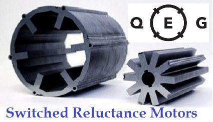
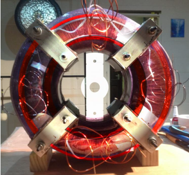
The QEG is a Switched Reluctance Generator. A study that helps de-mystify how the QEG works.
We wanted to show that the technology behind the QEG is a very real, very practical mechanism. The only reason why it is not well known is because it has been suppressed and underutilized. However, with changing times and the increasing need for alternative forms of energy, the QEG technology is already being employed in major motor manufacturing companies and is still slated to dominate the renewable energy industry in the future despite newer technologies that are coming out. This is because of its simple construction and low manufacturing costs.
The following is the first full chapter of our QEG eBook published here in its entirety written by Dijon Rios (AKA Tivon Rivers). We wanted to publish this freely to provide a reference source to help bridge the gap in the further development and distribution of this alternative form of energy creation.
THE LEGACY
A brief history of the reluctance generator
By Dijon Rios, Space Visuals Seaside Engineer
The generator build in this course is of the ‘reluctance’ type, and
can also be defined as a variant of the following: variable induction
generator and flux alternator. To better understand why this class of
generator is slated to still dominate the clean tech sector (in spite of
new technologies), we must first recap the development of this
technology.A brief history of the reluctance generator
By Dijon Rios, Space Visuals Seaside Engineer
An electric motor is an electrical machine that converts electrical energy into mechanical energy. Electric motors produce either linear or rotary force (torque), and are found in the following applications: industrial fans, pumps, machine tools, household appliances, power tools, and disk
drives. They can be powered by either direct current sources (i.e batteries, motor vehicles or rectifiers), or by alternating current sources (such as from the power grid, inverters or generators). General-purpose motors with highly standardized dimensions and characteristics provide convenient mechanical power for industrial use. The largest of electric motors are used for ship propulsion, pipeline compression and pump applications with ratings approaching 100 megawatts. Electric motors are classified by electric power source type, internal construction,
application, type of motion output, and so on.
Generators are motors operated in reverse, whereby it is an electrical machine that converts mechanical energy into electrical energy. Hence, to understand the origin of the reluctance generator, we must delve into the 125 year history of the reluctance motor and why this technology is anticipated to still dominate the renewable energy market in the 21st century.
In the 1880s, many inventors were trying to develop workable AC motors because of AC’s advantages in long distance high voltage transmission. In 1888, Nikola Tesla presented his paper ‘A New System for Alternating Current Motors and Transformers’ to the American Institute of Electrical Engineers (AIEE) and described three patented two-phase four-stator-pole motor types: one with a four-pole rotor forming a non-self-starting reluctance motor, another with a wound rotor forming a self-starting induction motor, and a third truly synchronous motor with separately excited DC supply to rotor winding.
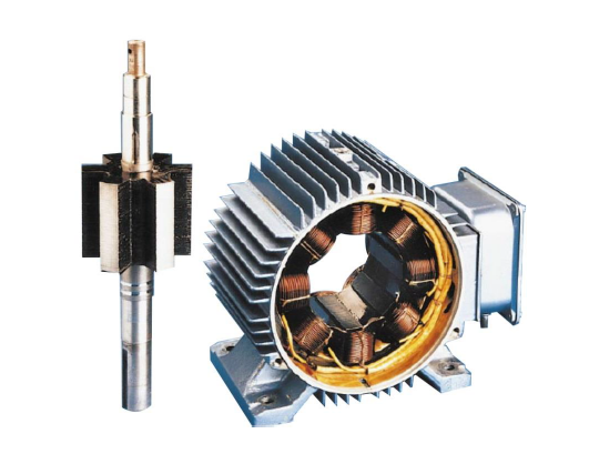
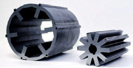
Switched reluctance motors have a rotor that has no magnets or windings. It is a salient piece of iron. The salient stator has a simple construction.
The design for the reluctance motor was first cited in patent 381,968 May 1, 1888 by the inventor Nikola Tesla. He conceived of an embodiment of a variable inductance motor with no magnets, and where the iron rotor contained no windings. The modern day Switched Reluctance Motor (SRM) remains true to Tesla’s patent, as it contains no brushes or permanent magnets, and the rotor has no electric currents. Instead, torque comes from a slight misalignment of poles on the rotor with poles on the stator. The rotor aligns itself with the magnetic field of the stator,
while the stator field stator windings are sequentially energized to rotate the stator field. The magnetic flux created by the field windings follows the path of least magnetic reluctance, meaning, the flux will flow through poles of the rotor that are closest to the energized poles of the stator, thereby magnetizing those poles of the rotor and creating torque. As the rotor turns, different windings will be energized, keeping the rotor turning.
Clean technology is a contemporary issue, and the international community has accepted the environmental dangers of false economies and the toxification of the environment. Renewable energy is one of the hot topics when it comes to a viable solution, and both wind and solar generation are but a few of the renewable energy power sources that help.
In recent decades, reluctance machines have become an important alternative in various applications in both the industrial and domestic markets. They have good mechanical reliability, high torque-volume ratio, high efficiency, plus low cost. Although the technology is less evangelized as a generator, there are a few studies of its application in the aeronautical industry and in wind based energy applications.
Although the synchronous and induction machines dominate the market of wind energy applications, the reluctance machines are the subject of current investigation and are a valid alternative for this field. Compared with the classical solutions of machines integrated in wind applications, its simplified construction associated with the in existence of permanent magnets or conductors in the rotor results in lower manufacturing costs; in addition both the machine and the power converter are robust. The low inertia of the rotor also allows the machine to respond to rapid variations in the load.
Associated with these characteristics, reluctance machines may now employ electronic control systems that enable rapid changes in machine function such that its performance is optimized (making them Switched Reluctance Machines or ‘SRM’). The structure of reluctance technology is not as stiff as their synchronous counterparts, and due to its flexible control system; is capable of absorbing transient conditions, thus supplying more resilience to the mechanical system.
The machine has an inherent fault tolerance, especially when under an open-coil fault (in the windings) and in the power converter (external faults). Under normal operation, each phase of Switched Reluctance Generator (SRG) is electrically and magnetically independent from others.
Reluctance technology is generally felt to be louder than conventional machines, but this can be remediated with adequate mechanical design, which can do a lot to improve these figures. In addition, all reluctance generators have the following advantages:
-simple construction, low manufacturing cost, low inertia,
-fault tolerance and the ability to operate in a high temperature environment
-present R&D for drives in power source applications that include hybrid electric vehicles, aerospace power systems and wind engines.
The aerospace and automotive applications are characterized by high-speed operation. Constant mechanical power is provided over a wide speed range, while the wind energy applications are characterized by low-speed and high-torque operation.
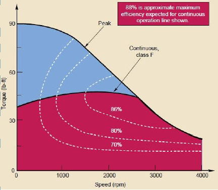
If 80% efficiency isn’t enough, know that companies are embracing this technology to position themselves in the renewables sector. For example HEVT has developed their switched reluctance motor technologies and are poised to empower the next generation of electric motors, making performance leaps with unmatched reliability and reduced cost volatility due to the use of zero rare earth minerals. They emphasize environmental benefits of having technologies that do not require the use of neodymium magnets in their statement:
“To date, most motors are manufactured in China because rare earth mining and refining capacity is concentrated in China. Mining and refining rare earth metals is a process that causes air, land and water pollution because these metals are typically located in bands of ore that include radioactive thorium. Not only do our technologies enable electric motors free of rare earth metals – thereby reducing environmental and public health impact – but the manufacturing process is disruptively elegant – we can scale production of our motors quickly and globally, creating local jobs in the process. Finally, our motors are highly reliable and efficient, high-performing and less costly: we reduce the initial and lifetime cost of ownership – a critical building block to enabling adoption of renewable energy, energy efficiency and sustainable transportation technologies in the U.S. and throughout the world.” – HEVT
You’ll learn how to build your own efficient reluctance generator.
Finally, by building the generator in this ebook you will be well positioned to participate in ongoing experiments in power regeneration research being undertaken worldwide. You will invariably test many configurations to get a better understanding of the methods other developers are using to recycle excess energy from the environment. There are generator builds that focus solely on the radiant techniques employed in countless Tesla patents, while others are using stored inertia in flywheels, gearing, and pendulums as an intermediary between the motor and generator as a means of an self-contained energy regeneration system (i.e. patents US 20080143302 A1 and ES2119690).
Get your copy of our eBook today!
Visit Space Visuals for more of Dijon Rios’s work
Breaking News: QEG Phase 3 Complete

The long awaited QEG Phase 3 Completion was announced today by Hope Girl of the Fix the World Organization. In her public statement on Youtube Hope states: “We are happy to announce, that we have cleared the last major hurdle to making the QEG self-sustain while providing additional power. After months of intensive work, under very difficult conditions, we have just now open sourced the final piece of information that QEG builders around the world will need to finish the machine.”
The last document of information for the QEG can be found on the Fix the World and Be-do.com website under title: “QEG Tuning & Technical Update Parts 1,2 and 3, and QEG Theory of Operation”
This is to be used in conjunction with the third edition manual that was released earlier in June.
This information is a step-by step detailed procedure for tuning the machine to enable the QEG to self-sustain with additional power output. There are as many as 70 (or more) QEG teams that are located around the world, and many more that wish to build that have been waiting for this final piece of information. QEG teams that are building were given this document last week prior to the public announcement to give them an opportunity to get started on the completion of their devices.
“The innovations that can be applied to this prototype going forward are numerous” explains Hope. “In staying with the true co-development nature of this endeavor, we are leaving these further innovations up to the creative expression of the engineers and inventors that are working on the QEG.”The QEG project started in September of 2013 with the first crowdfunding campaign to build the initial QEG prototype, which is a “Free Energy” device based on a Public Domain design of Nikola Tesla. The QEG is scaled large enough to power an average sized home.
The plans for building the prototype were opensourced on March 25th of 2014 which quickly went viral, and the QEG family traveled to build five different QEG’s in four countries in the later part of 2014. However, further development was needed to complete the project, and over the last year and a half, the QEG family has worked tirelessly in order to produce this final piece.
The Phase 3 Completion Documents along with the Third Edition Manual is open sourced and given freely given as a gift to the world. The project was made possible through the crowdfunding contributions of 1,212 people over the course of the last two years.
“We have also done tremendous work to set up the proper infrastructure for automated additional learning and distribution through our QEG eBook and a 10 week online video course,” Hope explains. “In addition, we have been raising funds to get all of this material translated into 10 different languages.” (That campaign can be seen at https://www.gofundme.com/qegrosettastone)The Fix the World Organization is now working on a revised business plan and seeking philanthropic benefactors to raise capital needs for a proper lab to further the development of the QEG and its numerous applications, and other technology devices meant to help people in need. The plan is to implement global projects from their headquarters in Morocco.
”To the best of our ability, and with great personal difficulty of our own, we have been able to deliver that which we set out to do. With this final piece we are now closing the PUBLIC PROJECT aspect of the QEG. As far as the FTW/QEG family team is concerned, any further innovations for the QEG and its development will be conducted in a privatized manner.”
“We have been applying a wide variety of entrepreneurial strategies in order to provide valuable products to people in order to raise the funds necessary for our greater purpose of a full-on humanitarian projects organization. We want to be ready for the financial shifts that are occurring in our world, so that we can present a detailed plan of implementation to any of the humanitarian projects funding that we’ve been hearing about through various channels.”To learn more about the QEG, please visit the following links:
“I can tell you that the last 2 years have been a real challenge for us and we have faced many great pains, losses and betrayals.” Explains Hope, “One thing I am forever grateful for is the obvious protection our family has received. For the people who believed in us, supported us, and were unwavering in their faith and dedication to this breakthrough: TODAY IS YOUR DAY. I give thanks to God that we have made it through, and that we still have each other and our integrity. Many people have died doing what we have done, and we are all still alive.”
Free Open Source QEG Manual
QEG Questions and Answers
QEG For Beginners Summary of Links
QEG eBook
The Underbelly of the QEG Project
QEG Consultations and Build Requests
FREE QEG Webinar Register July 20 2015
QEG Rosetta Stone Campaign
Fix the World Start up Campaign
FTW Memberships
FTW Business Plan and Benefactors
FTW/QEG Donations
Contact HopeGirl / FTW / QEG Team
Saturday, July 4, 2015
Sunday, May 3, 2015
Unraveling Nikola Tesla’s Greatest Secret: Radiant Energy

by Ken Adachi
If all the great inventions and discoveries of Nikola Tesla, nothing stood out with greater potential benefit to the whole of humanity than his discovery of Radiant Energy in 1889. The series of observations that led to the discovery of Radiant energy initially grew out of experiments that Tesla had conducted in an attempt to duplicate the results that Heinrich Hertz had claimed to achieve in affirming the existence of electromagnetic waves, the discovery of which Hertz announced in 1887. While replicating Hertz’s experiments, Tesla experimented with violently abrupt DC electrical discharges and discovered a new force in the process. Only after conducting exhaustive experimental trials for the next three years, did Tesla announce this stupendous discovery in a paper published in December, 1892, entitled “The Dissipation of Electricity”. Incredibly, most academicians of the day completely missed the mark in understanding the true significance of his paper. Noted scientists such as Sir Oliver Lodge, mistakenly thought that Tesla was referring to high frequency AC electricity in the operation of the Tesla Transformer, a huge blunder that remains to this day in the misnaming and misinterpretation of the Tesla Coil. The transformer that Tesla referred to in the 1892 paper did not operate on magnetic/electric field induction created by alternating currents. It operated in an entirely new domain of physics based on abrupt discharges of electrostatic potentials and the subsequent release of kinetic Radiant Energy from the omnipresent ether. Tesla was now operating under entirely new rules which he referred to as “dynamic” electro-static forces and had, by now, completely abandoned any further interest in the AC waveform. The genesis of the Lodge misunderstanding, however, began a few years earlier with the publication of certainmathematical formulas by a brilliant Scotsman named James Clerk Maxwell.
Maxwell’s Equations
Using mathematical models, James Clerk Maxwell had earlier suggested that two different types of electrical disturbances could possibly exist in Nature. One type was a longitudinal electric wave which required alternating concentrations of densified and rarefied pulsations of electrostatic fields that moved along a single vector (today, we refer to these as standing waves or scalar waves). Maxwell ultimately rejected this idea because he was convinced that this type of wave propagation was impossible to achieve, but his assumption was erroneous and would later portend formidable consequences for Tesla and the world at large.Maxwell’s second wave postulation was that of a transverse electromagnetic wave that exhibited a rapid alternation of electric fields along a fixed axis that radiated away from its point of origin at the speed of light and was detectable at great distances. Maxwell had more faith in the existence of this type of wave and encouraged experimenters to look in this direction. It was the discovery of this type of wave that Hertz had laid claim to, but Tesla was meticulous and fastidious in replicating Hertz’s experimental parameters and he could not obtain the results claimed by Hertz.
Tesla discovered a fundamental flaw in Hertz’s experiment: Hertz had failed to take into account he presence of air in his experiments. Hertz had mistakenly identified electrostatic inductions or electrified shockwaves as true electromagnetic waves. Tesla was saddened to bring this news to the distinguished academician, but felt scientific honesty was paramount if progress was to be achieved. Tesla visited Hertz in Germany and personally demonstrated the experimental error to him. Hertz agreed with Tesla and had planned to withdraw his claim, but reputations, political agendas, national pride, and above all, powerful financial interests, intervened in that decision and set the stage for a major rift in the ‘accepted’ theories that soon became transformed into the fundamental “laws” of the electric sciences that have held sway in industry and the halls of academia to the present day.
Tesla’s introduction to the phenomena of Radiant Energy began with early observations by linesmen working for Thomas Edison, Tesla’s former employer
DC Anomalies
Before Tesla’s invention of the Polyphase AC generator became the industry standard and overtook Thomas Edison’s use of DC generators, the DC electrical system was the only system available to deliver electricity to America’s homes and factories. Due to the resistance offered by long transmission lines, Edison had to produce very high DC voltages from his generators in order to deliver enough voltage and current to its final destination. He also had to provide additional ‘pumping’ stations along the way to boost the sagging voltage which dwindled from line losses. A curious anomaly occurred in the very first instant of throwing the power switch at the generating station: Purple/blue colored spikes radiated in all directions along the axis of the power lines for just a moment. In addition, a stinging, ray-like shocking sensation was felt by those who stood near the transmission lines. In some cases, when very large DC voltages surged from the generators, the “stinging” sensation was so great that occasionally a blue spike jumped from the line and grounded itself through a workman, killing him in the process.Tesla realized almost immediately that electrons were not responsible for such a phenomena because The blue spike phenomena ceased as soon as the current stated flowing in the lines. Something else was happening just before the electrons had a chance to move along the wire. At the time, no one seemed to be very interested in discovering why these dramatic elevations in static electrical potential were taking place, but rather, engineering design efforts were focused on eliminating and quenching this strange anomaly which was considered by everyone to be a nuisance-except Tesla. Tesla viewed it as a powerful, yet unknown form of energy which needed to be understood and harnessed if possible. The phenomena only exhibited itself in the first moment of switch closure, before the electrons could begin moving. There seemed to be a “bunching” or “choking” effect at play, but only briefly. Once the electrons began their movement within the wire, all would return to normal. What was this strange energy that was trying to liberate itself so forcefully at the moment of switch closure? .
Tesla, Genius Out of Time
In the later quarter of the 19th century, Tesla was alone in his opposition to the fundamental views of the nature of electrical forces as described by three of the biggest names in electric science: James Clerk Maxwell, Herman Von Helmholtz, and Heinrich Hertz. Tesla possessed a broader vision of the cosmos because his keen sense of awareness and especially his natural intuitive insights gave him a deeper understanding of the role that the ether (or aether) played in the manifestations of all electrical phenomena while his contemporaries focused their attention exclusively on the electromagnetic component (assuming that no other component could be involved). This lack of etheric insight by his contemporaries (with the exception of Sir William Crookes) and the heated controversy that the mere mention of the ether had engendered was to cause Tesla ridicule and sarcasm from men of inferior intellect for decades. The ether controversy largely dissipated in the academic arena after the publication of Eienstein’s Theory of Relativity (1905) and the Michaelson-Morley Experiment which essentially declared that the ether ‘theory’ was dead, but Tesla’s insights and deductions concerning the role of the ether were correct all along.This was the key that unlocked Radiant Energy.
“See the excitement coming!”
These were the words that Tesla used at the end of his pivotal 1892 December lecture, “The Dissipation of Electricity”. He was brimming over with buoyancy and optimism for the future In the 1890’s, Tesla conducted a large number of experiments which confirmed his theory and refined his understanding of the special conditions required for Radiant energy to express itself. He later expanded his New York work with the large scale experimental trials conducted at Colorado Springs, Colorado in 1899. Tesla, the humanitarian, wanted more than anything to share this enormous discovery with his fellow man. Tesla spoke of practical applications of radiant energy that were so wide reaching that they could have created a profound and immense leap into the future for all of mankind in practically every sector of daily life:Unlimited electricity could be made available anywhere and at any time, by merely pushing a rod into the ground and turning on the electrical appliance. Homes, farms, offices, factories, villages, libraries, museums, street lights, etc., could have all their lighting needs met by merely hanging ordinary light bulbs or fluorescent tubes anywhere desired- without the need for wiring -and produce brilliant white light 24 hours a day. Motor energy for any imagined use such as industrial applications, transportation, tractors, trucks, trains, boats, automobiles, air ships or planes could be powered freely-anywhere on the planet from a single Magnifying Transmitter. This new form of energy even had the ability to elevate human consciousness to levels of vastly improved comprehension and mental clarity. Undreamed of therapeutic applications to improve human health and to eliminate disease conditions could have been achieved fully 100 years ago had Tesla been allowed to complete his commercial development of Radiant Energy. But powerful barons of industry, chiefly in the person of John Pierpont Morgan, colluded to deny him the financial backing he needed and in doing so, effectively denied mankind one of Nature’s most abundant and inexhaustible gifts of free energy.
The Magnifying Transmitter

The closest Tesla came to a world wide industrial application of his Radiant Energy dream was the construction of his huge Magnifying Transmitter at Shoreham, Long Island, a site which he named Wardenclyffe. Following his return to New York City from Colorado Springs in 1899, Tesla was jubilant and full of enthusiasm to implement his plan for the commercial application of Radiant energy. He turned to JP Morgan for a substantial portion of the funding to finance the huge project at Wardenclyffe. Morgan was chiefly concerned with turning a profit from overseas radio transmissions since Marconi was fast locking up the market and Morgan, ever the aggressor, wanted a share of the market. When Tesla told him that the transmitter could transmit “intelligence” to the world, Morgan assumed that he meant ordinary radio communications, but Tesla was not referring to ordinary radio transmissions. He was talking about something much bigger, but avoided revealing all to Morgan during this early phase of the Wardenclyffe project. Some considerable time later, Tesla eventually felt compelled to tell Morgan the larger possibilities offered by the Magnifying Transmitter when he needed more funding to complete the project. Tesla thought that Morgan would be overwhelmed by his expanded explanation of the true capacities of the transmitter and would be anxious to complete the work, but Tesla’s assumption had backfired and Morgan refused to lay out any more money for the transmitter. Sadly, the enormous benefits that could have been made available to society by Tesla’s Magnifying Transmitter project, died then and there.
Morgan & Westinghouse
Morgan had already orchestrated circumstances in Tesla’s life in order to force Tesla to be dependent on him for financial backing. During an earlier period, when Tesla himself had millions from his Polyphase AC generator royalty payments and other earnings, Morgan wanted to woo Tesla with a deal that effectively gave Morgan majority control over his patent rights and projects, but Tesla turned him down, telling Morgan that he had enough money of his own to fund his projects. While returning to his hotel from that very meeting with Morgan, however, Tesla was told that his laboratory had been burned to the ground. It represented a tremendous loss to Tesla and it shook him deeply. Everyone, of course, felt convinced that Morgan was behind the arson. In order to save face, Morgan was embarrassed by Tesla into putting up the money to pay for the rebuilding of a new lab as an act of “philanthropy”. From that time forward, however, other financial backers were not to be found. Morgan was powerful enough to black list Tesla among the Eastern Establishment elites that previously had hobnobbed and feted with Tesla as if he was one of their own. Black listing and ostracization by officialdom and financiers lifted somewhat after Morgan’s death, but generally continued to haunt Tesla for the rest of his life.Before the turn of the century, Tesla also willingly gave up millions, perhaps billions, in royalty earnings to George Westinghouse in an unprecedented act of friendship. Westinghouse had believed in the superiority of Tesla’s AC system and provided the money to build Tesla’s big AC generators at Niagra Falls, NY. Tesla was paid millions up front for his patents, but was also due to receive royalty earnings for every kilowatt of power produced. When Westinghouse ran into financial difficulties at a later date, Tesla tore up his royalty contract in order to save Westinghouse from financial ruin. Had he not done that, Tesla would have had enough money from royalties to keep him ensconced in great wealth for the rest of his life.
The story is frequently told that when Morgan found out
from Tesla that the true purpose of the Wardenclyffe transmitter was to
provide free electricity to the world, he abruptly pulled the funding.
That’s not completely accurate. The economic conditions were
recessionary at the time and the stock market had taken a considerable
dip that year. Morgan wasn’t interested in risking any more capital in
perilous times on a project he couldn’t fully fathom and wasn’t
completely convinced of. Tesla held land ownership of the Wardenclyffe
site and tower, but no further work was done after 1910. In 1914, Tesla
was deeply in debt and signed over the deed of Wardenclyffe Station to
pay off years of back rent due to the owners of the New Yorker Hotel
where he was living (he occupied two penthouse suites in the hotel). In
1917, the hotel owners had the tower demolished and its parts sold for
salvage. Despite the loss of Wardenclyffe, Tesla continued to refine his
understanding of Radiant Energy and miniaturize the equipment needed to
produce it. He eventually was able to reduce the equipment down to the
size of a suit case.
Tuesday, April 28, 2015
Tesla Announces The Release Of A Battery That Can Power Your Home!
The wait is over! On April 30th, at its design studio in
Hawthorne, California, Tesla Motors Inc. will unveil its new product
line, and it’s not a car. In an email sent out to investors and
analysts on Tuesday, it was reported that Tesla would be announcing a
home battery and utility-scale battery.
Khobi Brooklyn, a Tesla spokeswoman, said that “we’ll share more information next week.”
We had gotten rumor of this new battery back in February when Elon Musk discussed it during an earnings call, but no additional details were made available at that time. In just under a week, we will finally be able get those details. How much will they cost? What hardware will be used and supported? Will these build upon the concepts in existing home batteries? Are they rechargeable? If not are they recyclable?
Tesla announced last September its plans to build a new Gigafactory in Reno, Nevada, 62 million has been spent so far. When all is said and done an estimated $5 billion will be spent on this project. Tesla plans to begin building lithium-ion batteries at this facility in 2017. The lithium-ion battery technology is being positioned to be the front runner in emerging energy storage that also provides supplementary electricity. Could this technology ultimately threaten our traditional electric grid? These new batteries when combined with the rapidly expanding residential solar market present exciting new opportunity’s for off the grid living.

Tesla has teamed up with SolarCity, a company chaired by Musk and ran by his cousin Lyndon Rive. Founded in 2006, the company has over 160,000 customers and controls almost 40% of the residential market. Solarcity installs panels for both commercial and residential applications and leases them for less than what you pay on your energy bill, and they sell surplus energy back to local utility’s. This model has proven to be extremely successful for SolarCity. They have begun installing Tesla batteries mostly in commercial buildings at this time. The batteries allow them to store excess energy for use during peak hours. This has shown to shave off 20-30 percent of energy bills. Solar City is currently running a pilot program with around 500 homes in California. The project is using 10-killowatt-hour battery packs that supply homes with about 2 days of power in the event of an outage.

Electric cars, space exploration, low-cost wireless internet for anyone, and now home batteries. Tesla Motors Inc has shown us that they are not just car makers, it begs to question what does Tesla have in store for the future?
Source: http://www.trueactivist.com/tesla-announces-the-release-of-a-battery-that-can-power-your-home/
Monday, April 27, 2015
John Ecklin's SAG 6
The Stationary Armature Generator 6, designed by John
Ecklin, is one among many of his inventions claimed to produce free
energy. It is a fascinating, ingeneous, and simple concept which might
or might not be over-unity, but is nonetheless worthwhile to
investigate.
I first learned about this device when I was thirteen, have made several attempts at building and testing it, and learned a few things not mentioned in any of the source articles—which is why it is included here.
To understand the generator, some simple electromagnetism principles need to be reviewed.
Faraday’s Law states that the voltage between the outputs of a coil is proportional to the rate at which the coil moves through a certain amount of magnetic flux. Thus, the stronger the magnet, the higher the number of loops in the coil, or the faster the coil cuts through magnetic flux, the greater the voltage generated. This really states that a changing magnetic field is required for a coil to tap its magnetic energy in the form of electricity.
An example of this is a loop of wire rotating like a spinning coin between opposite poles of a horseshoe magnet. Electricity is siphoned off the outputs of the coil.
Lenz’s law states that any coil of wire will set up an opposite magnetic field to counteract any change in its externally applied field. So if you bring the north pole of a magnet toward a coil’s end, the electricity induced within the coil sets up its own north magnetic field which repels the magnet, causing you to put more energy into bringing them closer. Then, if you pull the magnet away, the coil’s end becomes south and pulls you back.
An example of Lenz’s law is the following:
 Much energy is lost in pushing the coil toward and pulling it away from the magnet.
Ecklin’s SAG 6 attempts to circumvent Lenz’s law and produce electricity by combining two well known principles.
First, metal flying past a magnet loses no energy. The piece of metal velocity increases as it nears the magnet, and decreases as it leaves, but both in equal amounts. So from frame A to frame C, no energy is lost.
 You can prove this to yourself by tying a piece of metal to a
string, taping a button magnet to a table, and letting the metal swing
back and forth above the magnet. It does so for a long time, and only
slows down due to air friction and energy lost in the string’s
vibration.
You can prove this to yourself by tying a piece of metal to a
string, taping a button magnet to a table, and letting the metal swing
back and forth above the magnet. It does so for a long time, and only
slows down due to air friction and energy lost in the string’s
vibration.
Second, the following setup changes the magnetic polarity of a coil without the need of a moving magnet OR moving coil:
 Note that the only moving piece in this example is the shunt (piece
of magnetic metal), and as illustrated above, shunts lose no energy when
moving past a magnet. Still, from frame A to frame B, the magnetic
field within the coil changes, so electricity is produced.
Note that the only moving piece in this example is the shunt (piece
of magnetic metal), and as illustrated above, shunts lose no energy when
moving past a magnet. Still, from frame A to frame B, the magnetic
field within the coil changes, so electricity is produced.
Thus, because the shunts lose no energy, but electrical energy is still produced, this set up is theoretically over-unity.
The SAG 6 is cleverly designed like this:

 Here we have two opposite C-shaped magnets trying to influence the
magnetic polarity of the I-shaped core. Without the shunts, no magnetic
difference would exist between the top of the core and bottom. But since
every quarter turn one of the gaps between core and magnet is bridged
by a shunt, one magnet has greater influence over the core. By rotating
the shaft, the magnetic field within the core flips back and forth as
the strength of one magnet’s influence over the other switches back and
forth.
Here we have two opposite C-shaped magnets trying to influence the
magnetic polarity of the I-shaped core. Without the shunts, no magnetic
difference would exist between the top of the core and bottom. But since
every quarter turn one of the gaps between core and magnet is bridged
by a shunt, one magnet has greater influence over the core. By rotating
the shaft, the magnetic field within the core flips back and forth as
the strength of one magnet’s influence over the other switches back and
forth.
Because only the shunts are rotating, no energy is lost, and yet the I-shaped core still carries an alternating magnetic field whose energy is tapped by the coil wrapped around the core. The magnets and core remain stationary, hence the name “stationary” armature generator. Zero energy in + lots of energy out = free energy.
My first several models of this device were pathetic, for I had no experience in using the tools in my basement, but my sixth model was sturdy enough to prove one thing: the SAG 6 does indeed generate electricity without motion of magnets or core.
It lit a couple LED’s, but since there was so much friction, with such large airgaps, testing for over-unity was out of the question. An oscilloscope reading measured ant-hill shaped sine waves of three volts peak to peak. Output current was in the milliampere range. Since input power was around 30 watts, the efficiency of my model was miniscule. But it did produce electricity, which was hopeful.
Materials employed were a race-car motor, blue radioshack C-magnets and shunts, a core cut from a small transformer, 300 turns of #22 wire, brass shaft and slip bearings, and a battery charger to run the motor. This was done using elementary household tools, so I was not expecting much.
I have talked to David Colishaw, and he had built a model of the SAG 6, but his was also characterized by shoddy efficiency.
Now, the largest factor contributing to loss of generator efficiency is wider than acceptable air gaps. There is much magnetic flux leakage, and since the intensity of the magnetic field falls off as the square of distance, any air gap whatsoever will contribute to weakening of the magnetic field.
In the SAG 6, the air gap factor is employed to alternatingly weaken one of the magnet’s influence over the core—but look carefully at how the shunts are designed. They are solid pieces of soft iron, which actually channel the magnetic flux from the north pole to the south, leaving little for the core.
Thus, a more accurate picture of what happens in the SAG 6 is as follows:
 As you can see, the magnet with the stronger influence is the one
with a larger airgap. The size of this air gap is around .7 cm, and if
that is responsible for the strongest influence over the core, it is no
wonder my or David’s models had terrible efficiency. A generator with
air gaps larger than a quarter millimeter will undoubtedly fail at being
practical.
As you can see, the magnet with the stronger influence is the one
with a larger airgap. The size of this air gap is around .7 cm, and if
that is responsible for the strongest influence over the core, it is no
wonder my or David’s models had terrible efficiency. A generator with
air gaps larger than a quarter millimeter will undoubtedly fail at being
practical.
Why did Ecklin’s design incorporate this fault? Was Ecklin naive? It is a common practice for inventors of suppressed devices to publish their findings with an artificially inserted flaw, such that hired scientists of the “thought police” build the device, see it as faulty, and abandon their persecution of the inventor. The wise reader, however, would see the flaw, make the correction, and enjoy his over-unity model.
The corrected Ecklin generator would appear like so:

 Now, the shunts do not channel flux from north to south pole, but
from the poles to the core. With careful construction, airgaps may be
minimized, and friction reduced, leading to efficiencies hundreds to
thousands times better than my model. I have not built this modified
version yet, but will in due time.
Now, the shunts do not channel flux from north to south pole, but
from the poles to the core. With careful construction, airgaps may be
minimized, and friction reduced, leading to efficiencies hundreds to
thousands times better than my model. I have not built this modified
version yet, but will in due time.
From what has been said here, it would appear that the SAG6 is built upon sound theory. But a flaw in reasoning may still exist. Yes, a shunt will not lose energy when moving past a magnet…UNLESS the magnetic influence is diminished by an opposing magnetic field set up by the coil which cancels out the original field.
 As the shunt moves toward and away from the core, the pull of the
magnet may differ from frame A to frame C, such that extra energy is
required to pull the shunt away from the magnet after the field is first
weakened, then strengthened.
As the shunt moves toward and away from the core, the pull of the
magnet may differ from frame A to frame C, such that extra energy is
required to pull the shunt away from the magnet after the field is first
weakened, then strengthened.
This may be the achilles’ heel of Ecklin’s reasoning. It can’t be said for certain until models are built. From various articles written about this device, actual over-unity models have been constructed which perform as theorized, so perhaps it truly is genuine.
I first learned about this device when I was thirteen, have made several attempts at building and testing it, and learned a few things not mentioned in any of the source articles—which is why it is included here.
To understand the generator, some simple electromagnetism principles need to be reviewed.
Faraday’s Law states that the voltage between the outputs of a coil is proportional to the rate at which the coil moves through a certain amount of magnetic flux. Thus, the stronger the magnet, the higher the number of loops in the coil, or the faster the coil cuts through magnetic flux, the greater the voltage generated. This really states that a changing magnetic field is required for a coil to tap its magnetic energy in the form of electricity.
An example of this is a loop of wire rotating like a spinning coin between opposite poles of a horseshoe magnet. Electricity is siphoned off the outputs of the coil.
Lenz’s law states that any coil of wire will set up an opposite magnetic field to counteract any change in its externally applied field. So if you bring the north pole of a magnet toward a coil’s end, the electricity induced within the coil sets up its own north magnetic field which repels the magnet, causing you to put more energy into bringing them closer. Then, if you pull the magnet away, the coil’s end becomes south and pulls you back.
An example of Lenz’s law is the following:
Ecklin’s SAG 6 attempts to circumvent Lenz’s law and produce electricity by combining two well known principles.
First, metal flying past a magnet loses no energy. The piece of metal velocity increases as it nears the magnet, and decreases as it leaves, but both in equal amounts. So from frame A to frame C, no energy is lost.
Second, the following setup changes the magnetic polarity of a coil without the need of a moving magnet OR moving coil:
Thus, because the shunts lose no energy, but electrical energy is still produced, this set up is theoretically over-unity.
The SAG 6 is cleverly designed like this:
Because only the shunts are rotating, no energy is lost, and yet the I-shaped core still carries an alternating magnetic field whose energy is tapped by the coil wrapped around the core. The magnets and core remain stationary, hence the name “stationary” armature generator. Zero energy in + lots of energy out = free energy.
My first several models of this device were pathetic, for I had no experience in using the tools in my basement, but my sixth model was sturdy enough to prove one thing: the SAG 6 does indeed generate electricity without motion of magnets or core.
It lit a couple LED’s, but since there was so much friction, with such large airgaps, testing for over-unity was out of the question. An oscilloscope reading measured ant-hill shaped sine waves of three volts peak to peak. Output current was in the milliampere range. Since input power was around 30 watts, the efficiency of my model was miniscule. But it did produce electricity, which was hopeful.
Materials employed were a race-car motor, blue radioshack C-magnets and shunts, a core cut from a small transformer, 300 turns of #22 wire, brass shaft and slip bearings, and a battery charger to run the motor. This was done using elementary household tools, so I was not expecting much.
I have talked to David Colishaw, and he had built a model of the SAG 6, but his was also characterized by shoddy efficiency.
Now, the largest factor contributing to loss of generator efficiency is wider than acceptable air gaps. There is much magnetic flux leakage, and since the intensity of the magnetic field falls off as the square of distance, any air gap whatsoever will contribute to weakening of the magnetic field.
In the SAG 6, the air gap factor is employed to alternatingly weaken one of the magnet’s influence over the core—but look carefully at how the shunts are designed. They are solid pieces of soft iron, which actually channel the magnetic flux from the north pole to the south, leaving little for the core.
Thus, a more accurate picture of what happens in the SAG 6 is as follows:
Why did Ecklin’s design incorporate this fault? Was Ecklin naive? It is a common practice for inventors of suppressed devices to publish their findings with an artificially inserted flaw, such that hired scientists of the “thought police” build the device, see it as faulty, and abandon their persecution of the inventor. The wise reader, however, would see the flaw, make the correction, and enjoy his over-unity model.
The corrected Ecklin generator would appear like so:
From what has been said here, it would appear that the SAG6 is built upon sound theory. But a flaw in reasoning may still exist. Yes, a shunt will not lose energy when moving past a magnet…UNLESS the magnetic influence is diminished by an opposing magnetic field set up by the coil which cancels out the original field.
This may be the achilles’ heel of Ecklin’s reasoning. It can’t be said for certain until models are built. From various articles written about this device, actual over-unity models have been constructed which perform as theorized, so perhaps it truly is genuine.
Thomas Townsend BROWN Gravitator
"How I Control
Gravitation"
by
T.T. Brown
Science & Invention (August 1929) / Psychic Observer 37(1)
There is a decided tendency in the physical sciences to unify the great basic laws and to relate, by a single structure or mechanism, such individual phenomena as gravitation, electrodynamics and even matter itself. It is found that matter and electricity are very closely related in structure. In the final analysis matter loses its traditional individuality and becomes merely an "electrical condition." In fact, it might be said that the concrete body of the universe is nothing more than an assemblage of energy which, in itself, is quite intangible. Of course, it is self-evident that matter is connected with gravitation and it follows logically that electricity is likewise connected. These relations exist in the realm of pure energy and consequently are very basic in nature. In all reality they constitute the true backbone of the universe. It is needless to say that the relations are not simple, and full understanding of their concepts is complicated by the outstanding lack of information and research on the real nature of gravitation.
The theory of relativity introduced a new and revolutionary light to the subject by injecting a new conception of space and time. Gravitation thus becomes the natural outcome of so-called "distorted space." It loses its Newtonian interpretation as a tangible mechanical force and gains the rank of an "apparent" force, due merely to the condition of space itself.
Fields in space are produced by the presence of material bodies or electric charges. They are gravitational fields or electric fields according to their causes. Apparently they have no connection one with the other. This fact is substantiated by observations to the effect that electric fields can be shielded and annulled while gravitational fields are nearly perfectly penetrating. This dissimilarity has been the chief hardship to those who would compose a Theory of Combination.
It required Dr. Einstein's own close study for a period of several years to achieve the results others have sought in vain and to announce with certainty the unitary field laws.
Einstein's field theory is purely mathematical. It is not based on the results of any laboratory test and does not, so far as known, predict any method by which an actual demonstration or proof may be made. The new theory accomplishes its purpose by "rounding out" the accepted Principles of Relativity so as to embrace electrical phenomena.
The Theory of Relativity thus supplemented represents the last word in mathematical physics. It is most certainly a theoretical structure of overpowering magnitude and importance. The thought involved is so far reaching that it may be many years before the work is fully appreciated and understood.
Early Investigations ~
The writer and his colleagues anticipated the present situation even as early as 1923, and began at that time to construct the necessary theoretical bridge between the two then separate phenomena, electricity and gravitation. The first actual demonstration of the relation was made in 1924. Observations were made of the individual and combined motions of two heavy lead balls which were suspended by wires 45 cm. apart. The balls were given opposite electrical charges and the charges were maintained. Sensitive optical methods were employed in measuring the movements, and as near as could be observed the balls appeared to behave according to the following law: "Any system of two bodies possesses a mutual and unidirectional force (typically in the line of the bodies) which is directly proportional to the product of the masses, directly proportional to the potential difference and inversely proportional to the square of the distance between them."
The peculiar result is that the gravitational field of the Earth had no apparent connection with the experiment. The gravitational factors entered through the consideration of the mass of the electrified bodies.
The newly discovered force was quite obviously the resultant physical effect of an electro-gravitational interaction. It represented the first actual evidence of the very basic relationship. The force was named "gravitator action" for want of a better term and the apparatus or system of masses employed was called a "gravitator."
Figure 1 ~

Since the time of the first test the apparatus and the methods
used
have been greatly improved and simplified. Cellular "gravitators" have
taken the place of the large balls of lead. Rotating frames supporting
two and four gravitators have made possible acceleration measurements.
Molecular gravitators made of solid blocks of massive dielectric have
given
still greater efficiency. Rotors and pendulums operating under oil have
eliminated atmospheric considerations as to pressure, temperature and
humidity.
The disturbing effects of ionization, electron emission and pure
electro-statics
have likewise been carefully analyzed and eliminated. Finally after
many
years of tedious work and with refinement of methods we succeeded in
observing
the gravitational variations produced by the moon and sun and much
smaller
variations produced by the different planets. It is a curious fact that
the effects are most pronounced when the affecting body is in the
alignment
of the differently charged elements and least pronounced when it is at
right angles.
Much of the credit for this research is due to Dr. Paul Biefield, Director of Swazey Observatory. The writer is deeply indebted to him for his assistance and for his many valuable and timely suggestions.
Gravitator Action an Impulse ~
Let us take, for example, the case of a gravitator totally immersed in oil but suspended so as to act as a pendulum and swing along the line of its elements.
Figure 2 ~

When the direct current with high voltage (75-300 kilovolts) is
applied
the gravitator swings up the arc until its propulsive force balances
the
force of the earth's gravity resolved to that point, then it stops, but
it does not remain there. The pendulum then gradually returns to the
vertical
or starting position even while the potential is maintained. The
pendulum
swings only to one side of the vertical. Less than five seconds is
required
for the test pendulum to reach the maximum amplitude of the swing but
from
thirty to eighty seconds are required for it to return to zero.
Figure 3 ~

The total time or duration of the impulse varies with such cosmic
conditions
as the relative position and distance of the moon, sun and so forth. It
is in no way affected by fluctuations in the supplied voltage and
averages
the same for every mass or material under test. The duration of the
impulse
is governed solely by the condition of the gravitational field. It is a
value which is unaffected by changes in the experimental set-up,
voltage
applied or type of gravitator employed. Any number of different kinds
of
gravitators operating simultaneously on widely different voltages would
reveal exactly the same impulse duration at any instant. Over an
extended
period of time all gravitators would show equal variations in the
duration
of the impulse.
Figure 4 ~

After the gravitator is once fully discharged, its impulse
exhausted,
the electrical potential must be removed for at least five minutes in
order
that it may recharge itself and regain its normal gravitic condition.
The
effect is much like that of discharging and charging a storage battery,
except that electricity is handled in a reverse manner. When the
duration
of the impulse is great the time required for complete recharge is
likewise
great. The times of discharge and recharge are always proportional.
Technically
speaking, the exo-gravitic rate and the endo-gravitic rate are
proportional
to the gravitic capacity.
Summing up the observations of the electro-gravitic pendulum the following characteristics are noted:
APPLIED VOLTAGE determines only the amplitude of the swing.
APPLIED AMPERAGE is only sufficient to overcome leakage and maintain the required voltage through the losses of the dielectric. Thus the total load approximates on 37 ten-millionths of an ampere. It apparently has no other relation to the movement at least from the present state of physics.
MASS of the dielectric is a factor in determining the total energy involved in the impulse. For a given amplitude an increase in mass is productive of an increase in the energy exhibited by the system (E = mg).
DURATION OF THE IMPULSE with electrical conditions maintained is independent of all of the foregoing factors. It is governed solely by external gravitational conditions, positions of the moon, sun, etc., and represents the total energy or summation of energy values which are effective at that instant.
Figure 5 ~

GRAVITATIONAL ENERGY LEVELS are observable as the pendulum returns
from
the maximum deflection to the zero point or vertical position. The
pendulum
hesitates in its return movement on definite levels or steps. The
relative
position and influence of these steps vary continuously every minute of
the day. One step or energy value corresponds in effect to each cosmic
body that is influencing the electrified mass or gravitator. By merely
tracing a succession of values over a period of time a fairly
intelligible
record of the paths and the relative gravitational effects of the moon,
sun, etc., may be obtained.
In general then, every material body possesses inherently within its substance separate and distinct energy levels corresponding to the gravitational influences of every other body. these levels are readily revealed as the electro-gravitic impulse dies and as the total gravitic content of the body is slowly released.
Figure 6 ~

The gravitator, in all reality, is a very efficient electric
motor.
Unlike other forms of motors it does not in any way involve the
principles
of electromagnetism, but instead it utilizes the newer principles of
electro-gravitation.
A simple gravitator has no moving parts but is apparently capable of
moving
itself from within itself. it is highly efficient for the reason that
it
uses no gears, shafts, propellers or wheels in creating its motive
power.
It has no internal resistance and no observable rise in temperature.
Contrary
to the common belief that gravitational motors must necessarily be
vertical-acting
the gravitator, it is found, acts equally well in every conceivable
direction.
While the gravitator is at present primarily a scientific instrument, perhaps even an astronomical instrument, it also is rapidly advancing to a position of commercial value. Multi-impulse gravitators weighing hundreds of tons may propel the ocean liners of the future. Smaller and more concentrated units may propel automobiles and even airplanes. Perhaps even the fantastic "space cars" and the promised visit to Mars may be the final outcome. Who can tell?
British Patent # 300,311 (Nov. 15, 1928)
A Method of & an Apparatus or Machine for Producing Force or Motion
The invention also relates to machines or apparatus requiring electrical energy that control or influence the gravitational field or the energy of gravitation; also to machines or apparatus requiring electrical energy that exhibit a linear force or motion which is believed to be independent of all frames of reference save that which is at rest relative to the universe taken as a whole, and said linear force or motion is furthermore believed to have no equal and opposite reaction that can be observed by any method commonly known and accepted by the physical science to date.
The invention further relates to machines or apparatus that depend for their force action or motive power on the gravitational field or energy of gravitation that is being controlled or influenced as above stated; also, to machines or apparatus that depend for their force action or motive power on the linear force action or motive power on the linear force or motion exhibited by such machines or apparatus previously mentioned.
The invention further relates to machines and apparatus that derive usable energy or power from the gravitational field or from the energy of gravitation by suitable arrangement, using such machines and apparatus as first above stated as principal agents.
To show the universal adaptability of my novel invention, said method is capable of practical performance and use in connection with motors for automobiles, space cars, ships, railway locomotion, prime movers for power installations, aeronautics. Still another field is the use of the method and means enabling the same to function as a gravitator weight changer. Specific embodiments of the invention will be duly disclosed through the medium of the present Specification.
Referring to the accompanying drawings, forming part of this Specification:
Figure 1 is an elevation, with accompanying descriptive data, broadly illustrating the characteristic or essential elements associated with any machine or apparatus in the use of which the gravitational field or the energy of gravitation is utilized and controlled, or in the use of which linear force or motion may be produced.


by
T.T. Brown
Science & Invention (August 1929) / Psychic Observer 37(1)
There is a decided tendency in the physical sciences to unify the great basic laws and to relate, by a single structure or mechanism, such individual phenomena as gravitation, electrodynamics and even matter itself. It is found that matter and electricity are very closely related in structure. In the final analysis matter loses its traditional individuality and becomes merely an "electrical condition." In fact, it might be said that the concrete body of the universe is nothing more than an assemblage of energy which, in itself, is quite intangible. Of course, it is self-evident that matter is connected with gravitation and it follows logically that electricity is likewise connected. These relations exist in the realm of pure energy and consequently are very basic in nature. In all reality they constitute the true backbone of the universe. It is needless to say that the relations are not simple, and full understanding of their concepts is complicated by the outstanding lack of information and research on the real nature of gravitation.
The theory of relativity introduced a new and revolutionary light to the subject by injecting a new conception of space and time. Gravitation thus becomes the natural outcome of so-called "distorted space." It loses its Newtonian interpretation as a tangible mechanical force and gains the rank of an "apparent" force, due merely to the condition of space itself.
Fields in space are produced by the presence of material bodies or electric charges. They are gravitational fields or electric fields according to their causes. Apparently they have no connection one with the other. This fact is substantiated by observations to the effect that electric fields can be shielded and annulled while gravitational fields are nearly perfectly penetrating. This dissimilarity has been the chief hardship to those who would compose a Theory of Combination.
It required Dr. Einstein's own close study for a period of several years to achieve the results others have sought in vain and to announce with certainty the unitary field laws.
Einstein's field theory is purely mathematical. It is not based on the results of any laboratory test and does not, so far as known, predict any method by which an actual demonstration or proof may be made. The new theory accomplishes its purpose by "rounding out" the accepted Principles of Relativity so as to embrace electrical phenomena.
The Theory of Relativity thus supplemented represents the last word in mathematical physics. It is most certainly a theoretical structure of overpowering magnitude and importance. The thought involved is so far reaching that it may be many years before the work is fully appreciated and understood.
Early Investigations ~
The writer and his colleagues anticipated the present situation even as early as 1923, and began at that time to construct the necessary theoretical bridge between the two then separate phenomena, electricity and gravitation. The first actual demonstration of the relation was made in 1924. Observations were made of the individual and combined motions of two heavy lead balls which were suspended by wires 45 cm. apart. The balls were given opposite electrical charges and the charges were maintained. Sensitive optical methods were employed in measuring the movements, and as near as could be observed the balls appeared to behave according to the following law: "Any system of two bodies possesses a mutual and unidirectional force (typically in the line of the bodies) which is directly proportional to the product of the masses, directly proportional to the potential difference and inversely proportional to the square of the distance between them."
The peculiar result is that the gravitational field of the Earth had no apparent connection with the experiment. The gravitational factors entered through the consideration of the mass of the electrified bodies.
The newly discovered force was quite obviously the resultant physical effect of an electro-gravitational interaction. It represented the first actual evidence of the very basic relationship. The force was named "gravitator action" for want of a better term and the apparatus or system of masses employed was called a "gravitator."
Figure 1 ~
Much of the credit for this research is due to Dr. Paul Biefield, Director of Swazey Observatory. The writer is deeply indebted to him for his assistance and for his many valuable and timely suggestions.
Gravitator Action an Impulse ~
Let us take, for example, the case of a gravitator totally immersed in oil but suspended so as to act as a pendulum and swing along the line of its elements.
Figure 2 ~
Figure 3 ~
Figure 4 ~
Summing up the observations of the electro-gravitic pendulum the following characteristics are noted:
APPLIED VOLTAGE determines only the amplitude of the swing.
APPLIED AMPERAGE is only sufficient to overcome leakage and maintain the required voltage through the losses of the dielectric. Thus the total load approximates on 37 ten-millionths of an ampere. It apparently has no other relation to the movement at least from the present state of physics.
MASS of the dielectric is a factor in determining the total energy involved in the impulse. For a given amplitude an increase in mass is productive of an increase in the energy exhibited by the system (E = mg).
DURATION OF THE IMPULSE with electrical conditions maintained is independent of all of the foregoing factors. It is governed solely by external gravitational conditions, positions of the moon, sun, etc., and represents the total energy or summation of energy values which are effective at that instant.
Figure 5 ~
In general then, every material body possesses inherently within its substance separate and distinct energy levels corresponding to the gravitational influences of every other body. these levels are readily revealed as the electro-gravitic impulse dies and as the total gravitic content of the body is slowly released.
Figure 6 ~
While the gravitator is at present primarily a scientific instrument, perhaps even an astronomical instrument, it also is rapidly advancing to a position of commercial value. Multi-impulse gravitators weighing hundreds of tons may propel the ocean liners of the future. Smaller and more concentrated units may propel automobiles and even airplanes. Perhaps even the fantastic "space cars" and the promised visit to Mars may be the final outcome. Who can tell?
British Patent # 300,311 (Nov. 15, 1928)
A Method of & an Apparatus or Machine for Producing Force or Motion
I, Thomas Townsend Brown, a citizen of the USA,
do
hereby declare the nature of this invention and
in what manner the same is to be performed, to be
particularly described and ascertained in and by the following
statement:
---
This invention relates to a method of controlling
gravitation and for deriving power therefrom, and to a method of
producing
linear force or motion. The method is fundamentally electrical. The invention also relates to machines or apparatus requiring electrical energy that control or influence the gravitational field or the energy of gravitation; also to machines or apparatus requiring electrical energy that exhibit a linear force or motion which is believed to be independent of all frames of reference save that which is at rest relative to the universe taken as a whole, and said linear force or motion is furthermore believed to have no equal and opposite reaction that can be observed by any method commonly known and accepted by the physical science to date.
The invention further relates to machines or apparatus that depend for their force action or motive power on the gravitational field or energy of gravitation that is being controlled or influenced as above stated; also, to machines or apparatus that depend for their force action or motive power on the linear force action or motive power on the linear force or motion exhibited by such machines or apparatus previously mentioned.
The invention further relates to machines and apparatus that derive usable energy or power from the gravitational field or from the energy of gravitation by suitable arrangement, using such machines and apparatus as first above stated as principal agents.
To show the universal adaptability of my novel invention, said method is capable of practical performance and use in connection with motors for automobiles, space cars, ships, railway locomotion, prime movers for power installations, aeronautics. Still another field is the use of the method and means enabling the same to function as a gravitator weight changer. Specific embodiments of the invention will be duly disclosed through the medium of the present Specification.
Referring to the accompanying drawings, forming part of this Specification:
Figure 1 is an elevation, with accompanying descriptive data, broadly illustrating the characteristic or essential elements associated with any machine or apparatus in the use of which the gravitational field or the energy of gravitation is utilized and controlled, or in the use of which linear force or motion may be produced.
Figure 2 is a similar view of negative and
positive
electrodes with an interposed insulating member, constituting an
embodiment
of the invention.
Figure 3 is a similar view of a cellular
gravitator
composed of a plurality of cell units connected in series, capable of
use
in carrying the invention into practice.
Figure 4 is an elevation of positive and
negative
electrodes diagrammatically depicted to indicate their relation and use
when conveniently placed and disposed within a vacuum tube.
Figure 5 and 5' are longitudinal sectional views
showing
my gravitator units embodies in vacuum tube form wherein heating to
incandescence
is permitted as by electrical resistance or induction at the negative
electrode;
and also permitting, where desired, the conducting of excessive heat
away
from the anode or positive electrode by means of air or water cooling
devices.
Figure 6 is an elevation or an embodiment of my
invention
in a rotary or wheel type of motor utilizing the cellular gravitators
illustrated
in Figure 3.
Figure 7 is a view similar to Figure 6 of
another
wheel form or rotary type of motor involving the use of the gravitator
units illustrated in Figure 5, or Figure 5'.
Figure 8 is a perspective view partly in section
of
the cellular gravitator of Figure 3 illustrating the details thereof.
Figures 9, 10 and 10a are detail views of the
cellular
gravitator.
Figure 11 is a view similar to Figure 3 with the
same
idea incorporated in a rotary motor.
Figures 12 and 13 are detail views thereof.
The general showing in Figure 1 will make clear
how
my method for controlling or influencing the gravitational field or the
energy of gravitation, or for producing linear force or motion, is
utilized
by any machine or apparatus having the characteristics now to be
pointed
out.
Such a machine has two major parts A and B.
These
parts may be composed of any material capable of being charged
electrically.
Mass A and mass B may be termed electrodes A and B respectively.
Electrode
A is charged negatively with respect to electrode B, or what is
substantially
the same, electrode B is charged positively with respect to electrode
A,
or what is usually the case, electrode A has an excess of electrons
while
electrode B has an excess of protons.
While charged in this manner the total force of
A
toward B is the sum of force g (due to the normal gravitational
field) and force c (due to the imposed electrical field) and
force x
(due to the resultant of unbalanced gravitational forces caused by the
electronegative charge or by the presence of an excess of electrons on
electrode A and by the electro-positive charge or the presence of an
excess
of protons on electrode B.
By the cancellation of similar and opposing
forces
and by the addition of similar and allied forces the two electrodes
taken
collectively possess a force 2x in the direction of B. This
force
2x shared by both electrodes exists as a tendency of these
electrodes
to move or accelerate in the direction of the force, that is, A toward
B and B away from A. Moreover any machine or apparatus possessing
electrodes
A and B will exhibit such a lateral acceleration or motion of free to
move.
Such a motion is believed to be due to the direct control and influence
of the energy of gravitation by the electrical energy which exists in
the
unlike electrical charges present on the affected electrodes. This
motion
seems to possess no equal or opposite motion that is detectable by the
present day mechanics.
It is to be understood that in explaining the
theory
underlying my invention I am imparting by best understanding of that
theory,
derived from practical demonstration by the use of appropriate
apparatus
made in keeping with the teachings of the present Specification. The
practice
of the method, and apparatus aiding in the performance of the method,
have
been successful as herein disclosed, and the breadth of my invention
and
discovery is such as to embrace any corrected or more refined theory
that
may be found to underlie the phenomena which I believe myself to be the
first to discover and put to practical service.
In this Specification I have used terms as
"gravitator
cells" and "gravitator cellular body" which are words of my own coining
in making reference to the particular type of cell I employ in the
present
invention. Wherever the construction involves a pair of electrodes,
separated
by an insulating plate or member, such construction complies with the
term
gravitator cells, and when two or more gravitator cells are connected
in
series within a body, such will fall within the meaning of gravitator
cellular
body.
In Figure 2 the electrodes A and B are shown as
having
placed between them an insulating plate or member C of suitable
material,
such that the minimum number of electrons or ions may successfully
penetrate
it. This constitutes a cellular gravitator consisting of one gravitator
cell.
A cellular gravitator, consisting of more than
one
cell, will have the cell units connected in series. This type is
illustrated
in Figure 3, D being insulating members and E suitable conducting
plates.
It will be readily appreciated that many different arrangements for
cell
units, each possessing distinct advantages, may be resorted to.
One arrangement, such as just referred to, is
illustrated
in Figure 6of the drawings. Here the cells designated F are grouped in
spaced relation and placed evenly around the circumference of a wheel
G.
Each group of cells F possesses a linear acceleration and the wheel
rotates
as a result of the combined forces. It will be understood that, the
cells
being spaced substantial distances apart, the separation of adjacent
positive
and negative elements of separate cells is greater than the separation
of the positive and negative elements of any cell, and the materials of
which the cells are formed being the more readily affected by the
phenomena
underlying my invention than the mere space between adjacent cells, any
forces existing between positive and negative elements of adjacent
cells
can never become of sufficient magnitude to neutralize or balance the
force
created by the respective cells adjoining said spaces. The uses to
which
such a motor, wheel or rotor may be put are practically limitless, as
can
be readily understood without further description. The structure may
suitably
be called a gravitator motor of cellular type.
In keeping with the purpose of my invention, an
apparatus
may employ the electrodes A and B within a vacuum tube. This aspect of
the
invention is shown in Figures 4 and 5. In Figure 4 the electrodes are
such
as are adapted to be placed within a vacuum tube H (Figure 5), the
frame
and mounting being well within the province of the skilled artisan.
Electrons,
ions, or thermions can migrate readily from A to B. The construction
may
be appropriately termed an electronic, ionic, or thermionic gravitator
as the case may be.
In certain of the last named types of gravitator
units,
it is desirable or necessary to heat to incandescence the whole or part
of electrode A to obtain better emission of negative thermions or
electrons
or at least to be able to control that emission by variation in the
temperature
of said electrode A. Since such variations also influence the magnitude
of the longitudinal force or acceleration exhibited by the tube, it
proves
to be a very convenient method of varying the motion of the tube. The
electrode
A may be heated to incandescence in any convenient way as by the
ordinary
methods utilizing electrical resistance or electrical induction, an
instance
of the former being shown at J (Figure 5), and an instance of the
latter
at J' (Figure 5'), the vacuum tube in Figure 5' being designated H'.
Moreover, in certain types of the gravitator
units,
now being considered, it is advantageous or necessary also to conduct
away
from the anode of positive electrode B excessive heat that may be
generated
during the operation of tube H or H'. Such cooling is effected
externally
by means of air or water-cooled flanges that are in thermo connection
with
the anode, or it is effected internally by passing a stream of water,
air
or other fluid through a hollow anode made especially for that purpose.
Air cooled flanges are illustrated at K (Figure 5) and a hollow anode
for
the reception of a cooling liquid or fluid (as air or water) as shown
at
K' (Figure 5'). These electronic, ionic or thermionic gravitator units
may be grouped in any form productive of a desired force action or
motion.
One such form is the arrangement illustrated in Figure 7 where the
particular
gravitator units in question are indicated at L, disposed around a
wheel
or rotary motor similarly to the arrangement of the gravitator motor of
cellular type shown in Figure 6, the difference being that in Figure 7,
the electronic, ionic, or thermionic gravitator units are utilized.
This
motor may appropriately be designated as a gravitator motor of the
electronic,
ionic, or thermionic type, respectively.
The gravitator motors of Figure 6 and 7 may be
supplied
with the necessary electrical energy for the operation and resultant
motion
thereof from sources outside and independent of the motor itself. In
such
instances they constitute external or independently excited motors. On
the other hand, the motors when capable of creating sufficient power to
generate by any method whatsoever all the electrical energy required
therein
for the operation of said motors are distinguished by being internal or
self-excited. Here, it will be understood that the energy created by
the
operation of the motor may at times be vastly in excess of the energy
required
to operate the motor. In some instances the ratio may even be as high
as
a million to one. Inasmuch as any suitable means for supplying the
necessary
electrical energy, and suitable conducting means for permitting the
energy
generated by the motor to exert the expected influence on the same may
be readily supplied, it is now deemed necessary to illustrate the
details
herein. In said self-excited motors the energy necessary to overcome
the
friction or other resistance in the physical structure of the
apparatus,
and even to accelerate the motors against such resistance, is believed
to be derived solely from the gravitational field or the energy of
gravitation.
Furthermore, said acceleration in the self-excited gravitator motor can
be harnessed mechanically so as to produce usable energy or power, said
usable energy or power, as aforesaid, being derived from or transferred
by the apparatus solely from the energy of gravitation.
The gravitator motors function as a result of
the
mutual and unidirectional forces exerted by their charged electrodes.
The
direction of these forces and the resultant motion thereby produced are
usually toward the positive electrode. This movement is practically
linear.
It is this primary action with which I deal.
As has already been pointed out herein, there
are
two ways in which this primary action can accomplish mechanical work.
First,
by operating in a linear path as it does naturally, or second, by
operating
in a curved path. Since the circle is the most easily applied of all
the
geometric figures, it follows that the rotary form is the most
important.
While other forms may be built it has been considered necessary to
explain
and illustrate only the linear and rotary forms.
The linear form of cellular gravitator is
illustrated
in detail in Figures 8, 9 and 10. It is built up of a number of
metallic
plates alternated or staggered with sheets of insulating material
(Figure
3). Each pair of plates so separated by insulation act as one
gravitator
cell, and each plate exhibits the desired force laterally. The
potential
is applied on the end plates and the potential is divided equally among
the cells. Each metallic plate in the system possesses a force usually
toward the positively charged terminus, and the system as a whole moves
or tends to move in that direction. It is a linear motor, and the line
of its action is parallel to the line of its electrodes.
There are three general rules to follow in the
construction
of such motors. First, the insulating sheets should be as thin as
possible
and yet have a relatively high puncture voltage. It is advisable also
to
use paraffin-insulated insulators on account of their high specific
resistance.
Second, the potential difference between any tow metallic plates should
be as high as possible and yet be safely under the minimum puncture
voltage
of the insulator. Third, there should, in most cases, be as many plates
as possible in order that the saturation voltage of the system might be
raised well above the highest limit upon which the motor is operated.
Reference
has previously been made to the fact that in the preferred embodiment
of
the invention herein disclosed the movement is toward the positive
electrode.
However, it will be clear that motion may be had in the reverse
direction
determined by what I have just termed "saturation voltage", by which is
meant the efficiency peak or maximum of action for that particular type
of motor; the theory, as I may describe it, being that as the voltage
is
increased the force or action increases to a maximum which represents
the
greatest action in a negative-to-positive direction. If the voltage
were
increased beyond that maximum the action would decrease to zero and
thence
to the positive-to-negative direction.
Referring more specifically to Figures 8, 9 and
10,
red fiber end plates 1 act as supports and end insulators, and the
first
metallic plate 2 (for example aluminum) is connected electrically,
through
the fiber end plate, with the terminal 5. The second insulating sheet 3
is composed, for example, of varnished cambric, sometimes known as
"empire
cloth". The relative size and arrangement of the metallic plate and
insulating
sheets are best seen in Figures 9 and 10. A paraffin filler H is placed
between adjacent insulating sheets and around the edges of the metallic
plates (Figure 10a) and 6 represents a thin paraffin coating over the
whole
motor proper. 7 and 8 indicate successive layers of "empire cloth" or
similar
material, and 9 is a binding tape therefore. A thin film of a substance
such as black spirit varnish 10 protects and insulates the entire outer
surface. A phosphor bronze safety gap element 11 is connected
electrically
with the terminal (not shown) opposite to the terminal 5. A safety gap
element corresponding with the element 11 is electrically connected
with
the terminal 5, but it has not been shown, in order better to
illustrate
interior parts. The purpose of the safety gaps is to limit the voltage
imposed on the motor to the predetermined maximum and to prevent
puncture.
The rotary motor (Figures 11, 12 and 13)
comprises
broadly speaking, an assembly of a plurality of linear motors, fastened
to or bent around the circumference of a wheel. In that case the wheel
limits the action of the linear motors to a circle, and the wheel
rotates
in the manner of a fireworks pinwheel. The illustrations I have given
are
typical. The forms of Figur3s 6 and 7 have been defined. In Figure 11,
the insulating end disk 1a has an opening 2a therethrough for an
extension
of the shaft 12. The disk 1a is secured to a suitable insulating motor
shell, by fiber bolts or screws in any convenient manner, there being
another
of these disks at the opposite end of the shell, in the same manner as
the opposite end plates 1 in Figure 8. The cells are built upon an
insulating
tube 11a disposed about the shaft-space 3a. Thick insulating wedges 4a
separate the four linear motors illustrated. These thick insulating
wedges,
so-called, are substantially greater in body than the aggregate
insulating
sheets of the units. In some instances, however, dependent upon
materials
employed for the charged elements and the insulating members, this need
not necessarily be the case. In each motor of this circular series of
motors,
there are the alternate sheets of insulation 5a associated with the
alternate
metallic plates 6a; paraffin fillers 71 along the edges of the plates
6a
and between the insulating sheets 5a being employed similarly to the
use
of paraffin in Figure 8. The rotary motor is encircled by metallic
(preferably
copper) collector rings 10a, which are connected with the end metallic
plates of the separate linear motors at 9a and 13 (Figure 12), one of
these
connections 9 being shown in detail where the insulating tube is cut
away
at 8 (Figure 11).
It is unnecessary herein to illustrate a housing
or
bearings because any insulated housing and good ball bearings,
conveniently
supplied, will complete the motor. The potential is applied to the
safety
gap mounted on the housing and thence is conducted to the collector
rings
of the motor by means of sliding brushes.
While I have in the foregoing Specification
outlined,
in connection with the broader aspects of my invention, certain forms
and
details, I desire it understood that specific details have been
referred
to for the purpose of imparting a full and clear understanding of the
invention,
and not for the purposes of limitation, because it should be apparent
that
many changes in construction and arrangement, and many embodiments of
the
invention, other than those illustrated, are possible without departing
from the spirit of the invention or the scope of the appended claims.
Having now particularly described and
ascertained
the nature of my said invention and in what manner the same is to be
performed,
I declare that what I clam is:
(1) A method of producing force or motion, which
comprises
the step of aggregating the predominating gravitational lateral or
linear
forces of positive and negative charges which are so cooperatively
related
as to eliminate or practically eliminate the effect of similar and
opposing
forces which said charges exert.
(2) A method of producing force or motion, in
which
a mechanical or structural part is associated with at lest two
electrodes
or the like, of which the adjacent electrodes or the like have charges
of differing characteristics, the resultant, predominating
uni-directional
gravitational force of said electrodes or the like being utilized to
produce
linear force or a motion of said part.
(3) A method according to Claim 1 or 2, in which
the
predominating force of the charges or electrodes is due to the normal
gravitational
field and the imposed electrical field.
(4) A method according to Claim 1, 2, or 3, in
which
the electrodes or other elements bearing the charges are mounted,
preferably
rigidly, on a body or support adapted to move or exert force in the
general
direction of alignment of the electrodes or other charge-bearing
elements.
(5) A machine or apparatus for producing force
or
motion, which includes at least two electrodes or like element adapted
to be differently charged, so relatively arranged that they produce a
combined
linear force or motion in the general direction of their alignment.
(6) A machine according to Claim 5, in which the
electrodes
are mounted, preferably rigidly, on a mechanical or structural part,
whereby
the predominating uni-directional force obtained from the electrodes or
the like is adapted to move said part or to oppose forces tending to
move
it counter to the direction in which it would be moved by the action of
the electrodes or the like.
(7) A machine according to Calim 5 or 6, in
which
the energy necessary for charging the electrodes of the like is
obtained
either from the electrodes themselves or from an independent source.
(8) A machine according to Claim 5, 6, or 7,
whose
force action or gravitational power depends in part on the
gravitational
field or energy of gravitation, which is controlled or influenced by
the
action of the electrodes or the like.
(9) A machine according to any of Claims 5 to 8,
in
the form of a motor including a gravitator cell or gravitator cellular
body, substantially as described.
(10) A machine according to Claim 9, in which
the
gravitator cellular body or an assembly of the gravitator cells is
mounted
on a wheel-like support, whereby rotation of the latter may be
effected,
said cells being of electronic, ionic or thermionic type.
(11) A method of controlling or influencing the
gravitational
field or the energy of gravitation and for deriving energy or power
therefrom
comprising the use of at least two masses differently electrically
charged,
whereby the surrounding gravitational field is affected or distorted by
the imposed electrical field surrounding said charged masses, resulting
in a uni-directional force being exerted on the system of charged
masses
in the general direction of the alignment of the masses, which system
when
permitted to move in response to said force in the above mentioned
direction
derives and accumulates as the result of said movement usable energy or
power from the energy of gravitation or the gravitational field which
is
so controlled, influenced, or distorted.
(12) A method of and the machine or apparatus
for
producing force or motion by electrically controlling or influencing
the
gravitational field or energy of gravitation, substantially as
hereinbefore
described with reference to the accompanying drawings.
Thursday, April 16, 2015
India Won't Suppress Tewari's Free Energy Generator
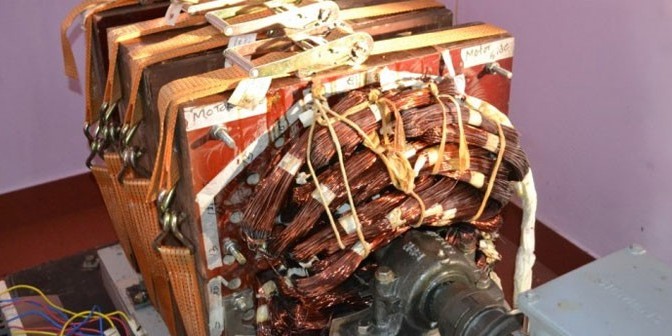
India Won’t Suppress Tewari’s Free Energy Generator
Years ago, Tewari had also proven the theories inside Bruce de Palma’s homopolar engine which first exposed this writer to the world of free energy technologies.
Obviously, a country cannot implement its own free energy program without considering all possible consequence including a military response from Petrodollar countries, e.g. Saudi Arabia, UK, US. That’s why India has been aligning its own military program with that of Russia which at present is standing up, together with the BRICS countries, against the Nazionist cabal that is imposing all sorts of sanctions to destroy the Russians.
The BRICS alliance has in the past promised to release all suppressed technologies, e.g. free energy, for our responsible utilization. It looks like they are keeping their word.
Breaking News: Over-Unity Reactionless Generator Invented In India
“Ere many generations pass; our machinery will be driven by a power obtainable at any point in the universe.” – Nikola Tesla
(Collective Evolution) A Reactionless AC Synchronous Generator (RLG) has been invented by Paramahamsa Tewari, electrical engineer and former Executive Director of Nuclear Power Corporation of India. His background includes engineering project management for construction of nuclear power stations. The efficiency of models he has built, which have also been independently built and tested, is as high as 250%.
In November 2014, I made one of many visits to the laboratory of Paramahamsa Tewari. I had seen the basis for the RLG design in September of 2010. Mr. Tewari showed me a stiff conductor about a foot long which was allowed to rotate at the center and connected at each end with small gauge wire. A magnetic circuit was placed under the conductor. When a current was allowed to flow through the conductor it rotated, due to a torque induced on the conductor according to Flemings Left Hand Rule and standard theory, verified by experiments at the dawn of the electrical age. With a simple rearrangement of the magnetic circuit, the same current produced no rotation – the torque was cancelled. I later duplicated the setup and experiment on my workbench. It is ingenious and lead to his breakthrough, the invention of a reactionless generator with greatly improved efficiency.

This experiment has lead to the design and testing of generators with efficiencies far above any previous design. The design uses the same types of materials used in current generators, but the magnetic circuit within the machine is configured to cancel back torque while inducing current and producing power. This might be compared to the rearrangement of materials by the Wright Brothers to build a surface with lift that resulted in manned flight in a time when many, including scientists, said it was impossible. Indeed, physicists who cling to an outdated model of the properties and structure of space have declared what has been done by Tewari to be impossible.
During the November testing I witnessed two tests of efficiency on the new model in Tewari’s lab. The second test was several percent better than the first and produced 6.6 KVA with an efficiency of 238%. A second set of stator coils was not connected yet but is expected to increase output to 300%. This is a 3 phase, 248 volt Hz, AC synchronous generator operating at 50 Hz. State of the art, true RMS meters on the input and output that measured KW, KVA, and power factor confirmed the readings of meters we had supplied for tests I observed in April of 2014.
We were able to visit a 130-acre factory site of one of the top electrical machinery manufacturing companies in India. At this site the company manufactures rotating electrical machines, including generators. When the chief electrical engineer first saw the drawings and design of the RLG he knew immediately what it meant for efficiency! Because of their confidence in the design, and the results of the tests on the smaller model, the company has assembled a self-excited machine designed to produce 20 KVA.
When we arrived at the factory a vice president of the company, the factory general manager, and the chief engineer greeted us. We then inspected the new machine and met the engineering design team assigned to this project. They are electrical and mechanical engineers who design and build conventional generators with output as high as 500 KVA. They are very enthusiastic and understand the breakthrough. A second machine rated at 25 KVA is now under construction at this company in India.

I believe, as do the engineers in India, that this is the biggest breakthrough in rotating electrical machine design since Faraday’s invention of the electrical motor in 1832. The elimination of back torque allows all the energy generated to pass through the machine. Power output is determined by the strength of the excitation magnets and the synchronous reactance (resistance at 50/60 Hz) of the stator windings. Current models can be cascaded for higher output. Each machine can produce at least 2.38 times the input and can be configured in a self-running mode. Due to concentration on efficiency and design improvements the machine has not yet been configured in this manner.
During a visit to witness tests in December of 2012, we were guests of the engineering director of a large utility company, and we toured a generation facility which the director pointed out was ready for RLG systems as soon as they are scaled to the required size. In March 2015 we returned to India for licensing discussions. Current plans call for introductory models to be marketed at 10 KVA and 25 KVA. A second company is involved in manufacturing discussions and the Karnataka Power Corporation, which supplies Bangalore, is investigating the use of 200 KVA units in a wind farm application as described in the April 7th edition of Asia Times.
The November 2013 issue of The Atlantic magazine features an article on The 50 Greatest Breakthroughs Since the Wheel. The RLG is more than just a product or a technical innovation. It is a fundamental change in the way that energy can be generated. It overcomes the inherent inefficiencies of AC generators. Patents have been filed and the RLG is ready to be licensed to companies that manufacture rotating electrical machinery. In fact, discussions with companies on three continents are underway.
We believe that the RLG is a fundamental discovery, not an innovation. Mankind’s first fundamental discovery was harnessing and controlling fire. The second was the wheel. The third was harnessing and controlling electricity. The fourth was harnessing and controlling the atom. The RLG can turn wheels without the use of fire (fossil fuels) or the atom (nuclear plants). It is a 21st century innovation. The first four of these innovations involved an understanding of material elements. The RLG is based on an understanding of the non-material properties of space. Paramahamsa Tewari’s search for the nature of reality has led him from study of the ancient Vedas of India to the formulation of Space Vortex Theory. It is a new theory unifying the relationship between space, mass, inertia, light, and gravity. Starting with principles described in the Vedic texts, Tewari was able to delineate a mathematical model that explains the words of Tesla when he said:
“All perceptible matter comes from a primary substance, or tenuity beyond conception, filling all space, the akasha or luminiferous ether, which is acted upon by the life giving Prana or creative force, calling into existence, in never ending cycles all things and phenomena.” – Nikola Tesla,“Man’s Greatest Achievement,” 1907
In Tewari’s words:
“The universal matter is created out of prana since prana is aakaash in motion, and aakaash is the primordial superfluid substratum of the universe.”
The concept that efficiencies cannot be greater than 100% is due to an incomplete understanding of the properties of space. The second law of thermodynamics must be modified to account for the fact that space is not empty, as has been taught for the last 150 years. The RLG operates at what has been called “over unity.” Many experienced electrical engineers engaged in the manufacture of AC generators have independently tested the RLG and confirmed the efficiency ratings that I have observed. It’s time for the physicists to get out of the way and modify their theories while the engineers go about the business of design and production.
The theory and mathematical models can be found at:
TEWARI.ORG
Recent Press Coverage:
Asia Times Article

Paramahamsa Tewari was born on June 1, 1937, and graduated in Electrical Engineering in 1958 from Banaras Engineering College, India, and held responsible positions in large engineering construction organizations, mostly in nuclear projects of the Department of Atomic Energy, India. He was also deputed abroad for a year at Douglas Point Nuclear Project, Canada. He is presently the retired Executive Nuclear Director, Nuclear Power Corporation, Department of Atomic Energy, India, and is the former Project Director of the Kaiga Atomic Power Project.
Fundamentals of physics attracted Tewari’s imaginations right from the early school and college days. Over the last four decades his new ideas on the basic nature of space, energy, and matter have solidified into definite shape from which a new theory (Space Vortex Theory) has emerged. The theory reveals the most basic issue of relationship between space and matter precisely pinpointing that space is a more fundamental entity than matter. The physical significance of mass, inertia, gravitation, charge and light are revealed by extending the analysis in the theory beyond material properties and into the substratum of space, which again is broken down into fieldless voids, thus showing the limit to which a physical theory can possibly reach. The real universe is shown to be opposite to the current concepts of concrete-matter and empty space. The books that he has authored on Space Vortex Theory are:
- The Substantial Space and Void Nature of Elementary Material Particles (1977)
- Space Vortices of Energy and Matter (1978)
- The Origin of Electron’s Mass, Charge Gravitational and Electromagnetic Fields from “Empty Space” (1982)
- Beyond Matter (1984)
 He
has lectured as invited speaker in international conferences in
Germany, USA, and Italy on the newly discovered phenomenon of Space
Power Generation. For the practical demonstration of generation of
electrical power from the medium of space, Tewari has built reactionless
generators that operate at over-unity efficiency, thereby showing
physicists have been wrong about the nature of space for 110 years and
he has shown that space is the source of energy for the generation of
basic forms of energy.
He
has lectured as invited speaker in international conferences in
Germany, USA, and Italy on the newly discovered phenomenon of Space
Power Generation. For the practical demonstration of generation of
electrical power from the medium of space, Tewari has built reactionless
generators that operate at over-unity efficiency, thereby showing
physicists have been wrong about the nature of space for 110 years and
he has shown that space is the source of energy for the generation of
basic forms of energy.Why There Will Be No Suppression Of New Energy Technology

It wasn’t long before carriage makers were driving horseless carriages. It wasn’t long before people crossing the continent on trains abandoned the railroads for airliners. Natural gas is replacing coal and there is nothing the railroads, the coal miners, or the coal companies can do about it. Cheaper and more efficient energy always wins out over more expensive energy. Coal replaced wood, and oil replaced coal as the primary source of energy. Anything that is more efficient boosts the figures on the bottom line of the ledger. Dollars chase efficiency. Inefficiency is suppressed by market forces. Efficiency wins in the market place.
The Engineering Director (electrical engineer) of the Karnataka Power Corporation (KPC) that supplies power to 6 million people in Bangalore and the entire state of Karnataka (10,000 megawatt load) told me that Tewari’s machine would never be suppressed (view the machine here). Tewari’s work is known from the highest levels of government on down. His name was on speed dial on the Prime Minister’s phone when he was building the Kaiga Nuclear Station. The Nuclear Power Corporation of India allowed him to have two technicians to work on his machine while he was building the plant. They bought him parts and even gave him a small portable workshop that is now next to his main lab.
Cropmton Greaves Ltd. (the GE of India) have funded his work and corporate directors CGL as well as Reliance (oil and energy) know of his work.
I have also been told by many Indians that the work of Tewari will never be suppressed. It is a matter of national pride. India is ready to take on the world. You can feel it everywhere you go. I realized, the first night here, while mediating at 3:00 AM in the morning, dealing with serious jet lag, that in just over 100 years. since Vivekananda came to the U.S. and introduced the west to Vedic teachings, that in every country of the world, during every minute and every second of the day or night, people are practicing yogic styles of meditation.
Bottom line; efficiency always wins. There will be no suppression of machines with efficiencies higher than those currently on the market.
The Best Way to Eliminate Carbon Emissions
- Eliminate Carbon Fuels.
- The USA has spent trillions of dollars on fossil fuels. Renewable Energy Systems have no fuel costs. A Utility that has no fuels costs can provide cheaper electricity and do it without releasing CO2
- Nothing Lasts Forever. Coal production has already peaked in terms of BTUs per pound. Peak Volumetric production is not far off, probably by 2025.
- If we do not use the energy we have now to build an energy system that does not rely on non-renewable energy, we will live in a preindustrial world when fossil fuels run out.
- We have a 50 year window to build a new energy system based on the worldwide fossil fuel depletion rate. We need to start now while protecting the health and safety of the coal miners, who will provide the energy we need to get the job done.
 Writen by Toby Grotz. (You can see a picture of him with Tewari here)
He is an electrical engineer and researcher of new energy technologies since 1973. He has organized numerous conferences and travelled the world interviewing and assisting inventors since 1992. He has been involved on both sides of the energy equation: exploring for oil and gas and geothermal resources and in the utility industry working in coal, natural gas, and nuclear power plants. While working in the aerospace industry, he worked on space shuttle and Hubble telescope testing in a solar simulator and space environment test facility. He has also been involved in research for new energy sources and novel forms of hydrogen production.
Collective Evolution
One of the significant sources of funds for the Cabal is the healthcare industry which registered a whopping $3.09 trillion in 2014, and is projected to soar to $3.57 trillion in 2017, in the US alone. We believe that this is just a conservative figure.
We can avoid using drugs, defeat any viral attack and scaremongering easily by knowing how to build our own comprehensive antiviral system. Find more about it here.
Subscribe to:
Posts (Atom)